What is a die casting mold? A die casting mold is a precision tool that shapes molten metal into finished parts under high pressure. The mold determines your part’s geometry, surface finish, dimensional accuracy, and production cost. For buyers, understanding mold structure helps you ask better questions, evaluate suppliers more effectively, and avoid costly mistakes.
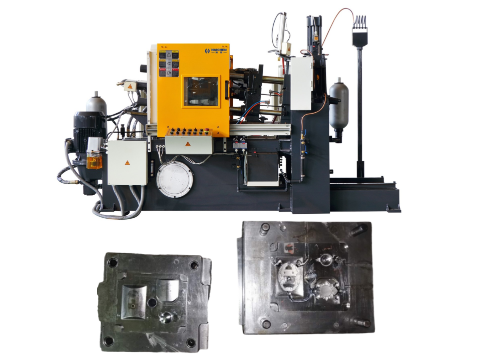
A die casting mold essentially consists of two main parts: the fixed mold half and the movable mold half. The fixed mold half mounts on the stationary platen and connects to the injection system through the sprue. The movable mold half attaches to the moving platen and carries the ejection system.
Beyond these two basic halves, a complete die casting mold includes several essential systems: the cavity and core that define the part shape, the gating system that guides metal flow, the cooling system that controls temperature, and the ejection system that pushes out finished parts. Let me walk you through each component in detail.
Fixed Mold Half vs. Movable Mold Half
The fixed mold half (stationary die) mounts on the machine’s fixed platen. It receives molten metal through the sprue – the entry channel that connects directly to the machine’s nozzle or pressure chamber. This half stays in place during the entire cycle.
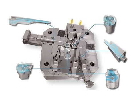
The movable mold half (ejector die) attaches to the machine’s moving platen. It carries the ejection system and pulls away from the fixed half after each cycle, allowing the part to be released. This half contains most of the cooling channels and the ejector pins.
What this means for you: The parting line – where these two halves meet – affects flash formation, gate placement, and part quality. Discuss parting line location with your supplier early in the design phase.
Cavity and Core System
The cavity forms the external shape of your part. The core creates internal features like holes, recesses, and undercuts. Together, they define the final geometry of every casting you produce.
Most molds use cavity inserts – separate pieces that bolt into the die halves. This design makes replacement easier and more cost-effective when specific sections wear out.
What this means for you: If your part design changes or a section wears prematurely, you can replace just the insert instead of the entire mold. This saves significant time and money.
Gating System: Sprue, Runners, and Gates
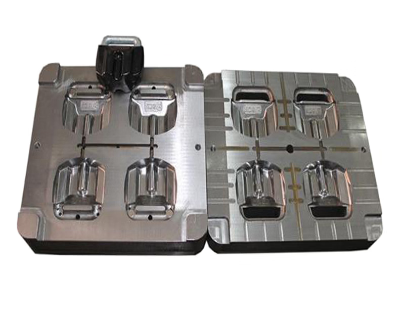
The gating system guides molten metal from the injection nozzle into the cavity. It consists of:
- Sprue: The main entry channel connecting to the machine’s nozzle
- Runners: Distribution channels that deliver metal to multiple cavities or specific areas
- Gates: Narrow openings that control metal flow into the cavity itself
This system directly affects pressure, speed, and filling pattern. Poor gate design causes turbulence, air entrapment, and cold shuts. Good gate design ensures smooth, complete filling every cycle.
What this means for you: Request gating system analysis from your supplier before they cut steel. Mold flow simulation helps identify potential filling problems early.
Overflow and Venting System
During injection, air and gases in the cavity must escape. The venting system provides thin channels for this purpose. Overflow slots trap the first metal that enters the cavity – the portion most likely to carry oxides and contaminants.
Proper venting prevents porosity – those tiny voids that weaken parts and cause leaks. In deep cavities, manufacturers often install vent plugs to improve evacuation.
Cooling System
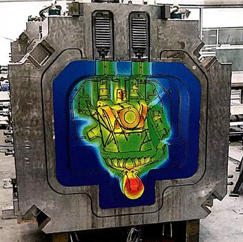
Temperature control directly determines cycle time and part quality. The cooling system uses water or oil channels machined into the mold to regulate temperature during each cycle.
Good cooling design:
- Reduces cycle time by speeding solidification
- Prevents hot spots that cause thermal fatigue
- Minimizes warping and distortion
- Extends mold life by reducing thermal stress
Advanced designs use conformal cooling – channels that follow the part contour for even more efficient heat removal.
What this means for you: Ask your supplier about their cooling channel design. Poor cooling leads to longer cycles, higher costs, and more defects.
Ejection System
After solidification, the ejection system pushes the part out of the mold. It includes:
- Ejector pins: Push against the part to release it
- Return pins: Push the ejector plate back after ejection
- Ejector plate: Holds and activates all ejector pins
Ejector pin placement affects your part’s cosmetic appearance. Pins leave small marks on the casting surface. Discuss acceptable locations with your supplier before finalizing the design.
Slides and Movable Cores
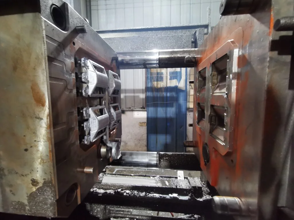
When your part has side holes, threads, or undercuts, you need slides (also called sliders or core pulls). These moving components retract sideways before the mold opens, allowing the part to eject cleanly.
How slides work: Slides retract quickly, often simultaneously with the die opening. Their effect on cycle time is negligible. Moving cores can help you avoid heavy casting sections, which results in faster cycle times.
Slides add complexity and cost to your mold. However, they are essential for many parts. Ask your supplier how they design slides to minimize wear and ensure reliable operation over thousands of cycles.
Mold Base and Support Structure
The mold base consists of steel plates and frames that hold everything together. It provides:
- Structural support for all components
- Mounting points for the die casting machine
- Alignment features (guide pins and bushings)
The mold base represents a significant portion of your total tooling cost. However, skimping on base quality risks misalignment, premature wear, and unsafe operation.
What Materials Are Die Casting Molds Made Of?
Most die casting molds use H13 hot-work tool steel. Manufacturers choose H13 because it resists thermal fatigue – the cracking caused by repeated heating and cooling cycles.
Other common materials include:
- H11: Similar to H13, also widely used
- P20 pre-hardened steel: Often used for zinc applications
- 3Cr2W8V and Cr12MoV: High-quality heat-resistant steels for cavity sections
- 40Cr and 30CrMnSi: Lower-cost options for short-run or prototype molds
What this means for you: For high-volume production, invest in premium materials like H13. The initial cost pays for itself through longer tool life and fewer replacements. For aluminum and magnesium casting, H13 is the standard choice. For zinc, P20 pre-hardened steel offers a cost-effective alternative.
Common Structural Forms of Die Casting Molds
The die casting mold’s structural form determines part quality, production efficiency, and mold cost. Common structural forms include:
Single-parting surface molds (two-plate molds) are the simplest and most common design. They feature one parting line where the two mold halves separate.
Double-parting surface molds (three-plate molds) have two parting lines. They allow more complex gating arrangements and are often used for multi-cavity molds.
Inclined core-pulling molds incorporate angled slides that move diagonally to form undercuts.
Multi-cavity molds produce multiple parts in a single cycle. They increase productivity but require more complex design and higher tooling costs.
What this means for you: The structural form you choose affects your tooling cost, cycle time, and part quality. Discuss these options with your supplier based on your production volume and part complexity.
Common Mold Problems and Solutions
Thermal Fatigue (Heat Checking)
Repeated heating and cooling causes microscopic cracks on the mold surface. These cracks eventually grow, degrading surface finish and part quality.
Solution: Optimize cooling channel design, control cycle temperatures, and use high-quality tool steel.
Soldering
Molten metal sticks to the mold surface, leaving deposits that damage the part and the tool.
Solution: Apply proper die lubricant, maintain correct temperatures, and use surface treatments like nitriding.
Erosion and Corrosion
High-velocity molten metal wears away mold material over time. Chemical reactions between metal and tool steel also cause corrosion.
Solution: Use erosion-resistant materials, optimize gate design to reduce velocity, and apply protective coatings.
Ejector Pin Problems
Pins can jam, break, or accumulate material buildup. This causes ejection failures and production delays.
Solution: Regular maintenance, proper lubrication, and timely replacement of worn pins.
Questions to Ask Your Mold Supplier
Before you place an order, ask these questions:
- “What material do you recommend for my production volume?” – High volume needs H13 or equivalent. Low volume may allow lower-cost options.
- “How do you design the cooling system?” – Look for suppliers who use conformal cooling or simulation tools.
- “Can you show me a mold flow analysis?” – This proves they understand filling dynamics.
- “What is your expected mold life?” – Get a clear number based on your alloy and cycle count.
- “How do you handle maintenance and repairs?” – Understand their support process before you need it.
- “What tolerances can you hold?” – Top suppliers achieve cavity machining within ±0.02mm.
- “Do you offer DFM (Design for Manufacturing) review?” – Early design input prevents costly changes later.
- “What structural form do you recommend for my part geometry?” – Single-parting, double-parting, or multi-cavity.
How Haichen Approaches Mold Design
Haichen brings a complete technical system to every mold project. Our process includes:
- Structural simulation before we cut any steel
- Material selection based on your specific production requirements
- Precision machining with tight tolerances
- Assembly and debugging to ensure proper function
- Ongoing support throughout the mold’s service life
We review mold flow analysis and product analysis reports early in the design phase. This catches potential problems before they become expensive mistakes.
Haichen produces both cold chamber and hot chamber die casting machines, and we supply complete mold solutions alongside our equipment. This integrated approach ensures compatibility and optimal performance.


