Die casting design is a complex process that requires comprehensive consideration of material properties, mold structure, process parameters and machine performance.
The core of die casting design lies in balancing material properties, mold structure, process parameters and economy. Through systematic processes (such as phased design, simulation verification) and experience accumulation.
When designing die casting, there are several tips to consider to ensure product quality and productivity.
Basic recommendations for die casting design
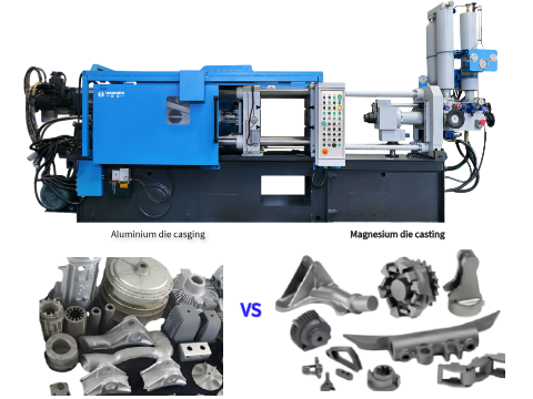
Here are some important design recommendations:
- Maintain uniform wall thickness
- Use rounded corners and transitions
- Add sufficient mould release slope
- Simplify the design
- Use ribs to reinforce the structure
- Avoid internal recesses and chamfers
- Consider the use of inserts
- Optimise the gate system
- Consider subsequent processing requirements
Maintain a uniform wall thickness
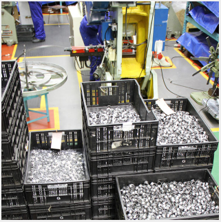
A uniform wall thickness helps the metal flow smoothly and reduces distortion due to cooling and shrinkage. For zinc alloy die castings, the wall thickness is usually between 1 and 1.5 mm, while aluminium or magnesium alloys should be 30 to 50 per cent thicker than zinc.
Use rounded corners and transitions
Sharp corners are to be avoided as they lead to stress concentrations and incomplete filling.
The design should use rounded corners or transitions to improve metal flow and product strength.
Add sufficient demoulding slope
Adding release slopes on surfaces parallel to the direction of mould opening helps to remove the casting easily after the mould is opened.
Simplify the design
Keep the design as simple as possible and avoid unnecessary protruding parts and complex shapes.
This will reduce the complexity of the mould and the production cost.
Use ribs to strengthen the structure
Use ribs where strength needs to be increased rather than increasing wall thickness, which reduces weight and improves structural performance.
Avoid internal recesses and chamfers
Try to avoid internal recesses and chamfers in the design as these add complexity to the mould and can lead to production difficulties.
Consider the use of inserts
Inserts can be used to spread loads and reduce stress concentrations, but it is important to ensure that they are securely fixed in the casting.
Optimise the gate system
A properly designed gate system ensures that the metal fills the mould cavity evenly and efficiently, thus avoiding defects.
Consider the need for subsequent machining
The design should consider whether subsequent machining is required, and leave enough metal allowance to meet the machining requirements.
By following these design principles, the quality and production efficiency of die castings can be improved while production costs are reduced.
The designer should work closely with the die casting manufacturer to ensure the feasibility of the design and the performance of the final product.
Wall Thickness in Die Casting Design Tips
The effect of wall thickness on mechanical properties and density is significant in the die casting design process.
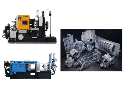
The following is a detailed analysis:
- Mechanical properties
- Density
- Process influence
- Design recommendations
Mechanical properties
Wall thickness has a direct effect on the mechanical properties of die castings.
Generally speaking, the thinner wall thickness die casting has higher strength and better density.
While thicker wall thickness die castings may lead to internal defects such as holes and shrinkage, thus reducing strength.
While thicker-walled die castings provide better resistance to deformation, they are prone to internal stress concentrations that can lead to cracks or deformation.
Therefore, there is a need to minimise the wall thickness and maintain a uniform wall thickness while ensuring adequate strength and stiffness at the time of design.
Density
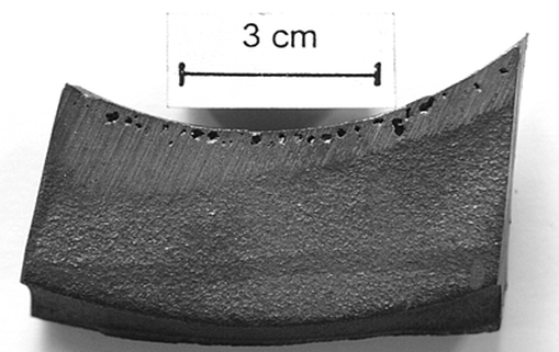
Thin-walled die castings usually have higher density.
Because they are able to form a finer grain structure in the cooling process, thus improving the overall strength and pressure resistance of the material.
Thick-walled die castings may result in coarser grain size due to slower cooling, which reduces the density and mechanical properties of the material.
Process influence
Uneven wall thicknesses can lead to inconsistent cooling rates, resulting in residual stresses and dimensional variations, which can affect the quality of the final product.
Thicker walled sections require longer cooling times, which can affect productivity and mould life.
Design recommendations
When designing die castings, the wall thickness should be kept as uniform as possible to avoid defects caused by uneven cooling.
For large die castings, a wall thickness of no more than 6 mm is usually recommended to avoid shrinkage holes and other defects.
The use of thin-wall design can effectively reduce weight and save material costs, but it is necessary to increase structural strength by means of reinforcing ribs and other means.
By reasonably controlling the wall thickness, it is possible to optimise the density and productivity of die castings while ensuring their mechanical properties.
The design needs to take into account the material properties, application requirements and process constraints in order to achieve the best die casting results.
Tips for designing Die Casting ribs
In die casting design, the design of reinforcement is an important means to improve the strength and rigidity of parts.
Here are some key tips and considerations about die casting reinforcement design:
- The role of reinforcement bar
- Strengthening bar size design
- Reinforcement bar arrangement principle
- The shape and connection of reinforcement
- Avoid flat design
- Other considerations
The role of reinforcement bar
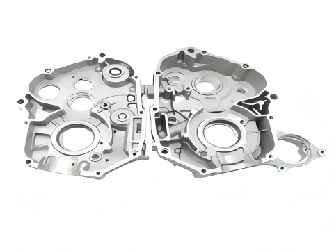
The main role of reinforcement bar is to increase the strength and rigidity of parts.
Prevent deformation of parts in the die casting process or post-processing.
In addition, the reinforcement can also assist the flow of molten metal, improve the filling performance of the casting.
The size design of the reinforcement bar
The thickness of the reinforcement bar should normally be less than 2/3 to 3/4 of the wall thickness where it is located.
The height of the reinforcement should not exceed 5 times its thickness.
The width of the reinforcement should not exceed half the thickness of the wall to which it is attached.
The release slope of the reinforcement is generally 1° to 3°, the higher the height, the smaller the release slope.
Principle of reinforcement arrangement
The distribution of reinforcing bars should be uniform and symmetrical, avoiding local over-thickness or over-density.
Avoid multiple reinforcement crossings to reduce stress concentration.
The direction of reinforcing bars should be consistent with the flow direction of molten metal to avoid metal flow disorder.
Shape and connection of reinforcing bars
The root of the reinforcing bar should be designed with rounded corners to avoid sharp changes in the cross-section of the part.
By this reduce stress concentration and improve the strength of the part.
For large plane or thin-walled die castings, the use of ‘S’ type or ‘U’ type and other special shape of the reinforcement can effectively prevent deformation and casting defects.
Avoid flat plate design
Flat plate design is easy to lead to low strength and deformation, so it is a better choice to improve the strength of the parts through reasonable setting of reinforcement.
Other considerations:
When the wall thickness is less than 1.5mm, it is not suitable to use reinforcement.
The design of reinforcing bar should consider the ejection position of the mould and the slope of demoulding to ensure smooth demoulding of the product.
Through these design tips and considerations, the structural design of die castings can be effectively optimised to improve its overall quality and performance.
Tips for optimal gate system design in die casting
In die casting process design, optimising the design of the gate system is a key step in improving casting quality and productivity.
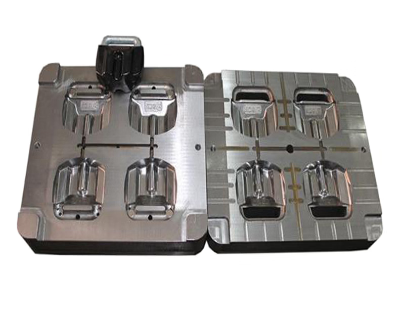
Here are some tips on how to optimise the gate system design:
- Selection of gate location
- Optimisation of runner cross-section shape and size
- Selection of gate form
- Design of overflow and venting tanks
- Use modern simulation software for optimization
- Adjustment of process parameters
- Avoid undesirable flow patterns
Selection of gate location
Choosing the right location for the gate is crucial to ensure that the metal liquid can fill the cavity evenly and quickly.
Normally, the gate should be set at the thickest part of the casting wall thickness.
In order to facilitate pressure transfer and reduce the formation of porosity, cold segregation and other defects.
In addition, the location of the gate should minimise the zigzag flow of the liquid metal to avoid eddy current phenomenon.
Optimisation of runner cross-section shape and size
Choose suitable runner cross-section shape (such as round, trapezoidal, rectangular, etc.) and size.
It can reduce the flow resistance of liquid aluminium alloy in the runner and improve the filling speed and pressure transfer efficiency.
For example, the design of conical straight sprue and inner sprue can ensure the speed and pressure of liquid steel in the pouring process.
Selection of gate form:
According to the specific requirements of the parts and mould structure characteristics to choose the appropriate form of gate.
Such as side gate, point gate, latent gate, etc., in order to obtain good moulding quality and mould life.
Compared with the side gates, the centre gate can effectively reduce the temperature reduction and kinetic energy loss of the liquid metal in the filling process, and reduce the defects of the products.
Design of overflow and venting tanks
The overflow tank is used to accommodate cold and dirty metal liquid and gas, preventing cold segregation, porosity and slag entrapment.
Adjust the temperature distribution of the mould to improve the heat balance.
The design of the exhaust tank needs to consider the impact of liquid metal, gas removal, dead zone diversion and other factors.
Use modern simulation software for optimisation
Modern die casting simulation software (such as ProCAST) can help to analyse the metal liquid flow and temperature field distribution.
Predict where defects are likely to occur and optimise the pouring system design.
Through numerical simulation, potential flow problems can be identified and solved, and internal gate guide angles or dimensions can be adjusted to achieve consistent filling.
Adjustment of process parameters
By adjusting process parameters such as injection speed, injection pressure, melt temperature and mould temperature.
It can improve the solid solution process and reduce casting defects.
For example, in high pressure die casting of magnesium alloys, by optimising these parameters, it is possible to generate a balanced flow rate and temperature distribution in the mould cavity.
Avoid undesirable flow patterns:
Optimisation of the gate design should avoid turbulence or uneven flow of the metal liquid as it enters the cavity.
This can lead to the formation of gas bubbles and oxide films, which can affect the quality of the casting.
The use of tilting pouring method or differential pressure casting process can fill the mould more smoothly and reduce defects.
Through the above measures, the design of die casting gating system can be effectively optimised to improve the quality and productivity of castings.


