Disadvantages of Die Casting Overflow:
- Waste of materials and consumption of resources
- Negative impact on mold life
- Product quality defects
- Constraints on production efficiency
- The cost of the economy is rising
- Environmental & Sustainability Impacts
Low silicon alloys are more sensitive to high metal speeds.
They stick to the mould quite quickly. To prevent sticking, the casting parameters must be adjusted to reduce the speed in the overflows.
This compromise usually means lower casting speeds and/or early break usage.
The result is often a lower-quality casting and no one wants that!
So, please check your overflow metal speeds in the simulation!
Product quality defects are also disadvantages of die casting overflow.
Die casting overflow grooves play an important role in improving casting quality.
Exhaust and thermal balance, there are many shortcomings in their design and application.
If you like insights like this, consider Haichen, our HPDC consulting package tailored to improving castings already in the sales process.
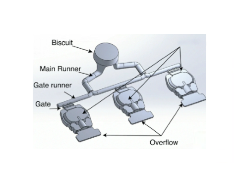
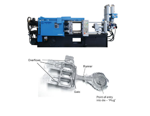
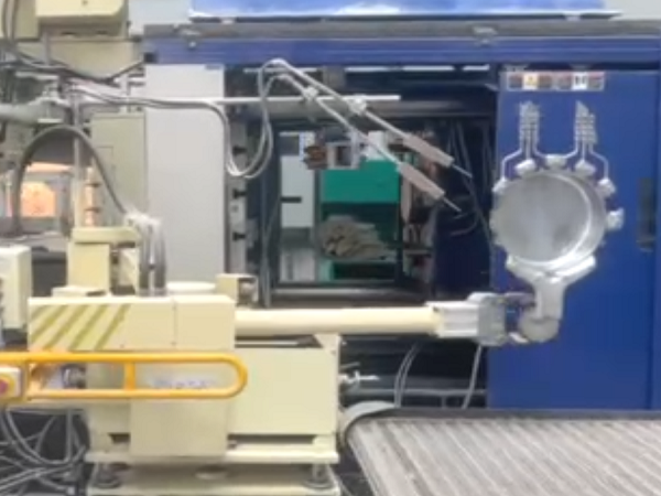
What is Overflow in Die Casting?
Overflow in die casting mold refers to the cavities and passages used as a vent for air escape and a trap for the flow of excess metal.
Die casting overflows can reduce the porosity in the die casting parts and assist the molten metal fill in the mold cavity.

Waste of materials and consumption of resources
- The overflow system has a high volume ratio
- Cold metal and impurity recovery issues
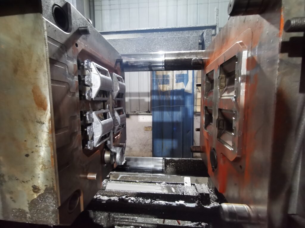
The overflow system has a high volume ratio
The volume of the overflow and gating system usually accounts for 20%-50% of the shot volume.
Especially in thin-walled castings, where the proportion of material in the overflow is higher.
Workers must remelt and dispose of these materials.
Which consumes additional energy (e.g., electricity) and generates material loss (e.g., oxide slag).
For example, the material of the overflow system can account for more than 40% of the total shot volume in thin-walled castings.
Cold metal and impurity recovery issues
The low-temperature metals or impurity-containing metals.
Such as oxides and paint residues received by the overflow tank are difficult to reuse directly.
And they need to undergo complex treatment before they can be put back into production.
Which increases the treatment cost.
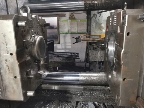
Negative impact on mould life
- Thermal stress and mold erosion
- Mechanical wear and washout
Thermal stress and mold erosion
The design of the overflow groove directly affects the thermal balance of the mold.
If the overflow area is locally overheated (e.g., the metal flow rate is too fast).
The thermomechanical stress on the mold surface will be exacerbated, resulting in thermal fatigue cracking or erosion.
For example, a study at the foundry in Italy found that cooling channels near the overflow chute that were too far from the mold surface significantly shortened the mold life.
Mechanical wear and washout
Improper design of the overflow (e.g., too wide or too thick) can cause high-velocity metal streams to wash the mold surface.
Accelerate wear of the cavity or vent groove, and even cause die washout defects.
Product quality defects
- Stomata and shrinkage porosity
- Inclusions and reflux contamination
- Surface defects and dimensional deviations
Stomata and shrinkage porosity
When the overflow system is not exhausted sufficiently, the gas tends to be trapped in the cavity and form porosity.
In addition, if the overflow tank solidifies prematurely, it cannot effectively discharge the front-end gas, resulting in shrinkage in critical areas of the casting.
Inclusions and reflux contamination
Cold metal or impurities in the overflow can flow back into the cavity through the overflow port.
Causing Inclusions or Flow Marks inside the casting.
For example, if the position of the overflow and exhaust grooves does not match.
The cold liquid can clog the exhaust channel, resulting in impurities remaining.
Surface defects and dimensional deviations
Excessive overflow velocity can cause metal splashes, form flashes at the parting line.
Or cause scratches and uneven texture on the casting surface.
Constraints on production efficiency
- Extended production cycles
- Commissioning and maintenance costs increase
Extended production cycles
Poor design of the overflow system can lead to longer filling times or frequent downtime to clean residues in the overflow tank.
For example, in the case of die-casting of a gearbox housing, the production cycle time was reduced by 15 percent after the overflow system was optimized.
Commissioning and maintenance costs increase
Complex overflow systems require more commissioning time.
And molds require frequent maintenance due to thermal stress or washout, further reducing equipment utilization.
The cost of the economy is rising
- Mold design and processing costs
- Material and energy costs
Mold design and processing costs
The optimal design of the overflow system requires numerical simulation (e.g., ProCAST, MAGMASOFT) and experimental verification, which increases the mold development cycle and cost.
For example, an oil pump cover mold used simulation to optimize the layout of the overflow groove, reducing development costs by 20%.
Material and energy costs
Material waste in the overflow system directly increases the cost per part.
In the case of aluminium alloys, the cost of handling returns increases by about $200-300 per ton.
Design Tips of Die Casting Overflow
- 1. Set it at the place where the metal flow initially impacts to exclude the condensed metal flow entering the cavity at the end, and the volume is slightly larger than the condensed metal flow.
- 2. It can be set at the place where the two metal flows meet to eliminate the cold insulation of die castings, and the volume is equivalent to the metal volume in the range of cold insulation.
- 3. It can be arranged around the cavity, and its volume shall be enough to remove the liquid metal mixed with gas and the gas in the cavity.
- 4. It can be set at the thick parts of die casting, and its volume is equivalent to 2-3 times the volume of hot joint or shrinkage defect.
- 5. It can be located where the vortex is easy to occur, and its volume is equivalent to the cavity volume of the vortex generating part.
- 6. Set it at the place where the mold temperature is low, and its volume is suitable to improve the mold temperature distribution.
- 7. It can be set at the dead corner on both sides of the inner gate, and its volume is equivalent to that of the die casting defect.
- 8. It can be set at the position with poor exhaust, and the push rod shall be set at the back.
- 9. Set an integral overflow tank to prevent deformation of die castings.
Environmental & Sustainability Impacts
The high proportion of overflow material re-furnace treatment not only increases carbon emissions (melting process), but can also lead to metal oxidation losses and affect resource utilization.
Afterwards,studies have shown that optimizing the overflow design can increase the material utilization rate by 10%-15%, which indirectly reduces the environmental burden.
Improvement direction and technical optimization
- Integrate mold flow analysis with intelligent design
- Vacuum die casting technology
- Gradient Materials & Coating Techniques
- Modular overflow design
Integrate mold flow analysis with intelligent design
The flow and temperature field of molten metal are simulated through ProCAST, FLOW-3D and other software.
And the position and size of the overflow tank are optimized to reduce the number of mold trials.
Vacuum die casting technology
Combined with a vacuum system for forced venting, it reduces reliance on overflow grooves, reduces scrap rates and improves surface quality.
Gradient Materials & Coating Techniques
Use heat-fatigue resistant H13 steel or surface nitriding treatment in the overflow groove area to extend mold life.
Modular overflow design
The replaceable insert structure is easy to maintain and adjust, and reduces the overall mold scrap rate.


