Gas Porosity refers to the bubbles or holes formed when the gas in the molten metal does not completely escape and solidifies during the die casting process.
Gas Porosity
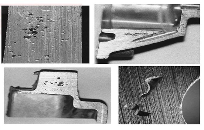
Morphology
Usually round or oval in shape, with a smooth surface and a diameter ranging from microns to millimeters.
Distribution
Due to the buoyancy of gases, it is mostly concentrated on the top of the casting or in the area near the surface.
Impact
Reduces the mechanical strength, air tightness and surface quality of the casting, and in severe cases, leads to scrapping of the workpiece.
The type of Gas Porosity
Flushed Porosity
Causes
The gas is encapsulated due to the turbulent flow of molten metal during high-speed injection.
And the gas in the mold cavity or material tube is not discharged in time.
Features
In general, the hole wall of this kind of stomata is smooth and regular-shaped.
And it is mostly distributed at the end of the filling path or in the complex structure area.
Intrusive porosity
Source
Vaporization of release agents, lubricating oils, etc., at high temperatures, or gas intrusion into the molten metal caused by the evaporation of residual water on the surface of the mold.
Performance
It often shows convex bubbles on the surface, and there is a clear boundary between the hole and the casting body.
Precipitated porosity
Mechanism
Cooling molten metal reduces solubility, causing dissolved hydrogen to precipitate into fine, scattered pinholes.
Characteristics
The inner wall is smooth and has a metallic luster, mostly seen in thick-walled or slow-cooling areas.
Reactive porosity
Inducement
A chemical reaction occurs at the interface between the molten alloy and the mold (e.g., aluminum reacts with water vapor to produce hydrogen).
Distribution
Mostly concentrated near the surface of the mold, irregular shape.

Causes of Gas Porosity
Molten metal precipitation gas (about 85%)
Hydrogen dissolution
The solubility of hydrogen in molten aluminum increases with the increase of temperature, and it precipitates to form pores when solidifying.
Contamination of raw materials
Moisture of alloy ingots, oil contamination in the return material or hygroscopic flux absorption, resulting in gas generation during melting.
Die casting process involves gas
High-speed filling
Liquid metal flows too fast causing turbulence, which rolls air into the cavity.
Poor mold exhaust
The exhaust channel is blocked or unreasonably designed, and the gas cannot escape.
The release agent breaks down the Gas Porosity
Excessive or improperly composed release agent (e.g., moisture) decomposes at high temperatures, producing gas.
Gas Porosity Testing Methods and Standards
Boyle’s Law
Calculates pore volume by measuring the pressure change of gas in the sample chamber with high accuracy and for irregular samples.
Mercury Intrusion Porosimetry
Pore distribution from 3 nm to 50 μm can be detected using the ability of mercury to penetrate pores under high pressure.
Physisorption
Evaluates micropore structures (<0.5 nm) using nitrogen/argon adsorption based on ISO 15901-2.
X-ray/Ultrasonic Flaw Detection
Quickly locate porosity position and size, suitable for mass production quality control.
Metallographic analysis
Distinguish between gas pores and shrinkage pores by microscopic observation of stomatal morphology.
Process Control Measures to Reduce Gas Porosity
Melting & Material Control Degassing Treatment
Reducing the hydrogen content of liquid aluminum to less than 0.1 mL/100g using a rotary degasser or vacuum degassing unit.
Raw material management
Alloy ingots need to be dried and stored, and the return material needs to be removed from oil stains and pre-baked.
Mold & Process Optimization
Exhaust system design: Set up the overflow groove and exhaust groove, and the cross-sectional area of the overflow groove should be ≥60% of the cross-sectional area of the product.
Vacuum-assisted technology is used to evacuate more than 90% of the air in the cavity.
Filling speed: For ADC12 aluminum alloy brackets, the optimal slow injection speed is 95 L/min.
Pouring temperature: It is recommended to control it at 640–670°C to balance fluidity and hydrogen precipitation.
Mold temperature: Maintain 200–220°C to avoid local overcooling and gas entrapment.
Release agent selection:Use a low-volatile, moisture-free formulation of the release agent and control the spray volume at 0.5–1.0 mg/cm².
Simulation software applications: Optimize the design of the gating system and cooling channels with software such as MAGMA to reduce turbulent areas.


