Optimize cooling in die casting is a central part of reducing cycle times and increasing efficiency.
Optimize cooling in die casting to reduce cycle times requires a multifaceted approach that combines mold design, material science, process control, and advanced technology.
Selection and combination strategy of Optimize cooling in die casting
Water
Application scenario: It is suitable for mold areas with large heat dissipation.
Such as cavities and near gates), and quickly distributes heat through cooling water circulation.
The channel diameter is recommended to be 8-16mm, and the distance from the cavity surface is 10-15mm to balance heat dissipation and mold strength.
Optimization direction
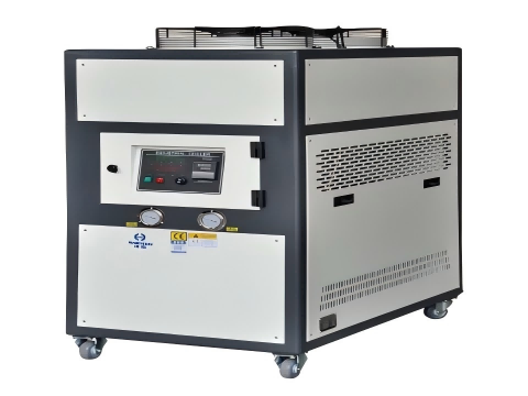
Multi-loop independent temperature control system is adopted to adjust the water temperature (10-95°C) in different regions to avoid the formation of scale.
Demineralized water treatment extends the life of the equipment.
Example
Core jet cooler with pore cooling can effectively cool down at a high temperature of 200°C.
Avoiding mold sticking and extending mold life.

Air-cooled
Application scenario
Used in areas where watercourses are difficult to lay out (such as thin walls or complex structures), and can also blow out the release agent and reduce porosity.
Optimization direction
Combined with compressed air directional injection, the local cooling rate is improved; It is linked to the painting process to reduce the consumption of additional time.
Heat pipe cooling
Principle: The high thermal conductivity of heat pipes is used to export heat from small areas.
Such as deep cavities, ribs to the external cooling system, which is suitable for miniature parts or high-precision molds.
Advantages: Solve the traditional cooling blind zone, reduce the risk of local overheating.
And shorten the overall solidification time.
Indirect cooling
Technical points
Thermal conductivity materials (such as copper alloys or aluminum alloys) are embedded in the hot joints to accelerate heat dissipation through heat conduction.
Design optimization
Combined with Conformal Cooling Channels, the flow channel is customized according to the shape of the cavity, and the heat transfer efficiency is improved by more than 20%.
Combination strategy
In most continuous production, water-cooled and air-cooled synergies are adopted, with water-cooled leading internal heat dissipation.
And air-cooled auxiliary surface cooling and process connection to form a uniform temperature field.
Key Parameter Optimization and Design Principles
Mold material selection
High thermal conductivity mold steels, such as H13, can improve heat dissipation efficiency.
But need to balance wear resistance with cost.
Copper alloy inserts are used for localized heat dissipation.
Cooling channel design
Geometrical parameters: channel diameter, spacing and distance from the cavity need to be optimized by CFD simulation.
Studies have shown that the short distance arrangement of 10.5mm pipe diameter can significantly reduce the cavity temperature gradient.
Layout principle: Spiral, serpentine and other flow channels are used to enhance the turbulence effect and avoid uneven cooling caused by straight channels.
Cooling medium control
Flow rate and temperature: Increasing the flow rate can speed up heat dissipation (e.g., a 50 L/h flow rate reduces the cycle time by 150 seconds).
But it is necessary to avoid turbulent resistance caused by too high a flow rate.
Media type: oil cooling or gas cooling is used for high-temperature areas (such as magnesium alloy molds) to prevent water from boiling; Water cooling in low-temperature areas improves economy.
Thermal balance calculations
Establish a mold thermal balance model, and dynamically adjust the cooling time and spraying cycle.
For example, infrared thermography can be used to identify critical cooling areas and reduce ineffective cooling times.
Integrated application of intelligent temperature control system
Closed-loop control system
Technical architecture: Integrate infrared temperature measurement, PID algorithm and actuator.
Such as mold temperature machine to achieve ± 0.1°C accurate temperature control.
For example, the ThermLoop system dynamically adjusts the multi-circuit parameters through a “temperature-controlled brain”.
Benefits: After an auto parts manufacturer introduced an intelligent system, the scrap rate was reduced by 30% and the production efficiency was increased by 20%.
Centralized temperature control solution
Case: Aode 3.0 version of the temperature control system integrates water temperature machine, oil temperature machine and spot cooling device.
Reducing power distribution power by 50%, energy consumption by 30%, and supporting 20-320°C wide-range temperature control.
Data-driven optimization
Process simulation: Software such as MAGMASOFT optimizes® cooling parameters through virtual DOE, reducing cycle times by more than 10%.
Real-time monitoring: Vacuum level monitoring and dynamic feedback system can compress the die casting cycle from 86 seconds to 66 seconds.
Mold design optimization
Balanced cooling system
Strategically placed cooling channels have uniform depth and spacing near the mold surface to ensure efficient heat dissipation.
Conformal cooling channels that follow the mold geometry reduce cycle times by up to 30% while improving temperature uniformity.

Thermal equilibrium
Different parts of the mold, such as cavities and cores, may require different cooling profiles.
Infrared imaging and thermocouples enable real-time monitoring to maintain a precise temperature range.
For example, zinc alloys (casting at 425°C) are good for rapid cooling due to their low melting point.
While aluminum alloys require controlled cooling to avoid defects such as solder adhesion.
Material selection
Materials with high thermal conductivity, such as copper alloys, enhance heat dissipation but require a cost-benefit analysis.
Beryllium copper molds can improve cooling efficiency by up to 50% compared to steel.


