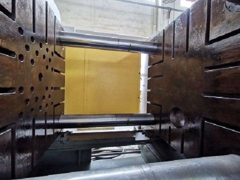
Tie bar in die casting machines are critical structural components that hold the die halves together under high pressure during the casting process.
They must be designed and specified to withstand significant clamping, cavity pressure, and thermal loads.
Proper design and material selection are essential to prevent failure, ensuring consistent die closure and preventing defects like flash.
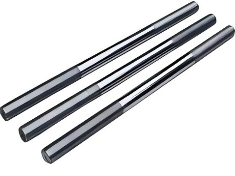
Haichen offers both nitrided rods and traditional chrome-plated rods, which are used in the manufacturing of press machines.
And also provides the production of guide rods, piston rods and other components for press machines.

Tie Bar in die casting core features
- Ejector pin reset and mold protection
- Mold positioning and stability
- Shock and shock absorption
Ejector pin reset and mold protection
The tie rod primarily ensures the forced return of the thimble during the die-casting process.
Thereby preventing stagnation or mold damage that could result from spring return failure.
Especially in high-speed continuous production, the precise reset of the ejector pin is the key to ensure the life of the mold.
Mold positioning and stability
By adjusting the spacing and verticality of the dynamic platen, the tie rod ensures the coaxiality of the mold when it is closed.
And avoids the misalignment of the parting surface caused by the installation deviation.
In some designs, the tie rod also has an integrated guide function to reduce the additional bending moment of the cantilever force on the tool.
Shock and shock absorption
In the high-pressure injection phase, the tie rod absorbs the shock load when the die is opened and closed.
Innovative designs such as tie rods with load relief grooves significantly increase flexural strength and fatigue life by optimizing stress distribution, reducing the risk of breakage.
Tie Bar Special application scenarios
Bending tie rod design: the oblique core pulling of the slider is realized by the bending structure.
Which is suitable for castings with deep cavities or lateral bosses.
Composite function: Some tie rods have the function of guiding and bearing cantilever forces.
And need to be optimized by large diameter design.
Key parameters of Tie Bar design
- Determination of diameter and length
- Strength and stability check
Determination of diameter and length
Bending stress, extrusion stress and wrapping force need to be taken into account.
For example, the diameter of the push rod in the die-casting mold of the cylinder end head is 18mm.
The effective mold opening stroke should be matched with the length of the core.
And a stop should be set at the end of the cable-stayed rod to enhance the rigidity.
Strength and stability check
The moment of the bending cross-section must, therefore, adjust the slender-to-length ratio of the push rod to prevent instability.
For bending tie rods, Haichen engineers always analyze both bending stress and tensile-compressive stress concurrently.
Furthermore, straight tie rods require rigorous stability assessments due to their axial loading characteristics.
Tie Bar in die casting Commonly used material types
Alloy steel: such as GLG345-GLG1100 grade, suitable for high-strength demand scenarios.
Stainless steel: BLG205-BLG1080 grade, excellent corrosion resistance.
Tungsten carbide: Outstanding wear resistance, widely used in high-wear areas.
Basis for material selection
According to Haichen’s experience, high-temperature working mold steels, such as H13 steel, have good high-temperature strength.
And they reduce friction resistance, with their service life exceeding 250,000 times.
Secondly, in terms of the balance between cost and performance, carbon tool steels have a lower cost.
However, it should be noted that although aluminum alloys are lightweight, they have lower strength.
Specification of Tie Bar structural design parameters
- Diameter-to-length ratio
- Optimization of retract groove
Diameter-to-length ratio
Typical tie rod diameters range from 50-600mm (steel); therefore, engineering standards recommend maintaining a length-to-diameter ratio of ≤20:1 to prevent buckling failure.
For example, the 1305mm long tie rod made of Q235B material needs to be ≥ 100mm in diameter to carry a load of 16.4kg.
Optimization of retract groove
The depth of the retract groove should be smaller than that of the load reduction groove (patented design).
The width ≥ 2 times that of the retract groove, and the radius of the transition arc ≥ 5 times the depth of the groove to disperse the stress.
Tie Bar in die casting Installation fit parameters
- Hole spacing
- Thread fit
Hole spacing
Given the proportional relationship between mold components.
Such as an 800mm rod and 500mm holes—strict adherence to tolerances (±0.5mm) is critical to prevent assembly failures.
Thread fit
The tie rod thread needs to be meshed in full length (such as M320×10 serrated thread).
And the lock nut needs to be double anti-loosening (spring gasket torque marking).
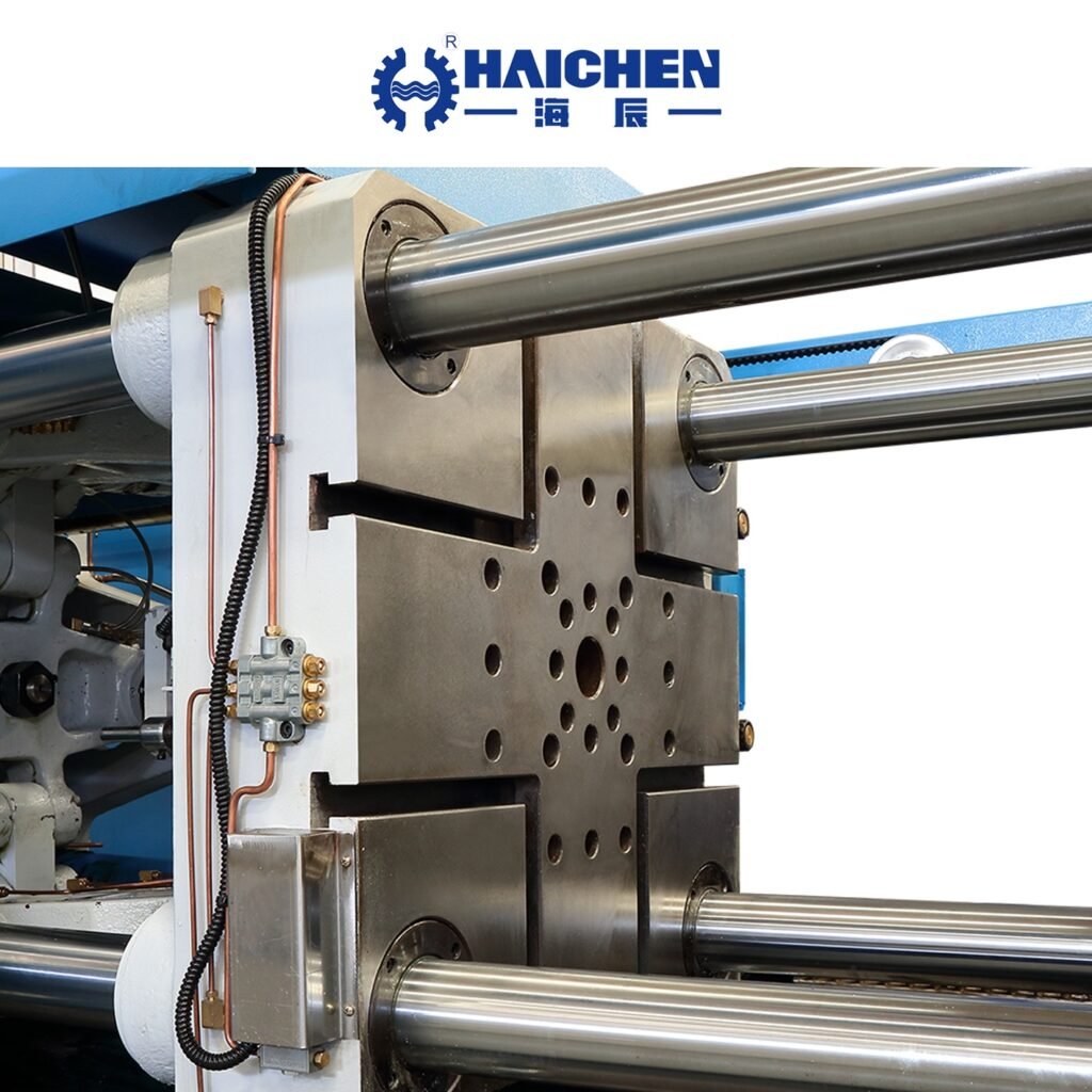
Tie Bar in die casting Installation and positioning specifications
To ensure uniform stress distribution on all four pull rods, align the mold expansion force’s center as precisely as possible.
The mold clamping device of the Haichen die-casting machine maintains a maximum deviation of 5 millimeters.
Regularly check the force error of the beam and adjust the position of the mold support.
To meet the specified tolerance requirement of ≤ 0.02 millimeters per meter.
The laser alignment instrument can actively calibrate the parallelism of the moving plate.
Ensure compliance with industry standards.
Fastening and sealing
The number of pressing plates is ≥ 2 on each side, the bolts are ≤ 50mm from the edge of the mold.
And the height of the cushion block is equal to the groove of the mold pressing plate to avoid stress concentration.
Operators should seal the cooling channel and tie rod hole independently to prevent corrosion caused by coolant infiltration.
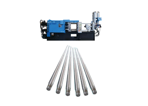
Haichen Tie Bar Specifications
Tie Bars are critical components in the clamping units of die-casting machines, engineered to provide strengthrigidity, and dimensional accuracy under high load conditions.
Each tie bar is induction hardened and precision around to ensureconsistent surface finish, extended durability, and superior alignment during operation.
Manufactured from premium-arade allousteels, these bars oer hioh tensle strenath,excelent fatiowe resistance, and uniform stress distribution
Designed to handle demanding mechanical environments, Tie Bars help maintain accurate mold positioning and ensure smoothclamping performance throughout prolonged production cycles.


