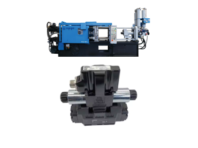
Hydraulic valves are the core control element of the hydraulic system of the die-casting machine.
And its failure directly affects the production efficiency and equipment safety.
In the die casting process, hydraulic valves are key components of the hydraulic system, responsible for controlling pressure, flow, and direction to ensure the proper operation of the die casting machine.
Faulty hydraulic valves can lead to production disruptions, reduced product quality, or equipment damage.
To troubleshoot hydraulic valve issues quickly, start by identifying common symptoms like leaks or low pressure.
Check for blockages, inspect seals, and ensure proper oil viscosity.
Regular maintenance and timely repairs can prevent recurring problems.
Let Haichen join you in delving deeper into the steps for efficiently diagnosing and repairing your hydraulic valves.
Why should the hydraulic valve be repaired if it has failed?
A hydraulic valve fails or malfunctions, most companies use a new component to restore the function of the hydraulic system, and the failed hydraulic valve becomes scrap.
In fact, most parts of these hydraulic valves are still in good condition and can be partially repaired to restore function.
Correct maintenance of hydraulic valves can save acquisition costs.
When replacing hydraulic valves, such as no spare parts, it takes a long time to order, and some imported valves are even difficult to buy.
So the equipment may be shut down for a long time, while the repair can restore the operation of the equipment and even the entire production line, the economic benefits are considerable.
If you are struggling with how to repair the hydraulic valve, why not contact Haichen?
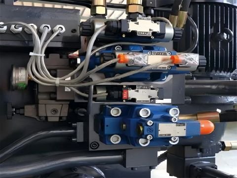
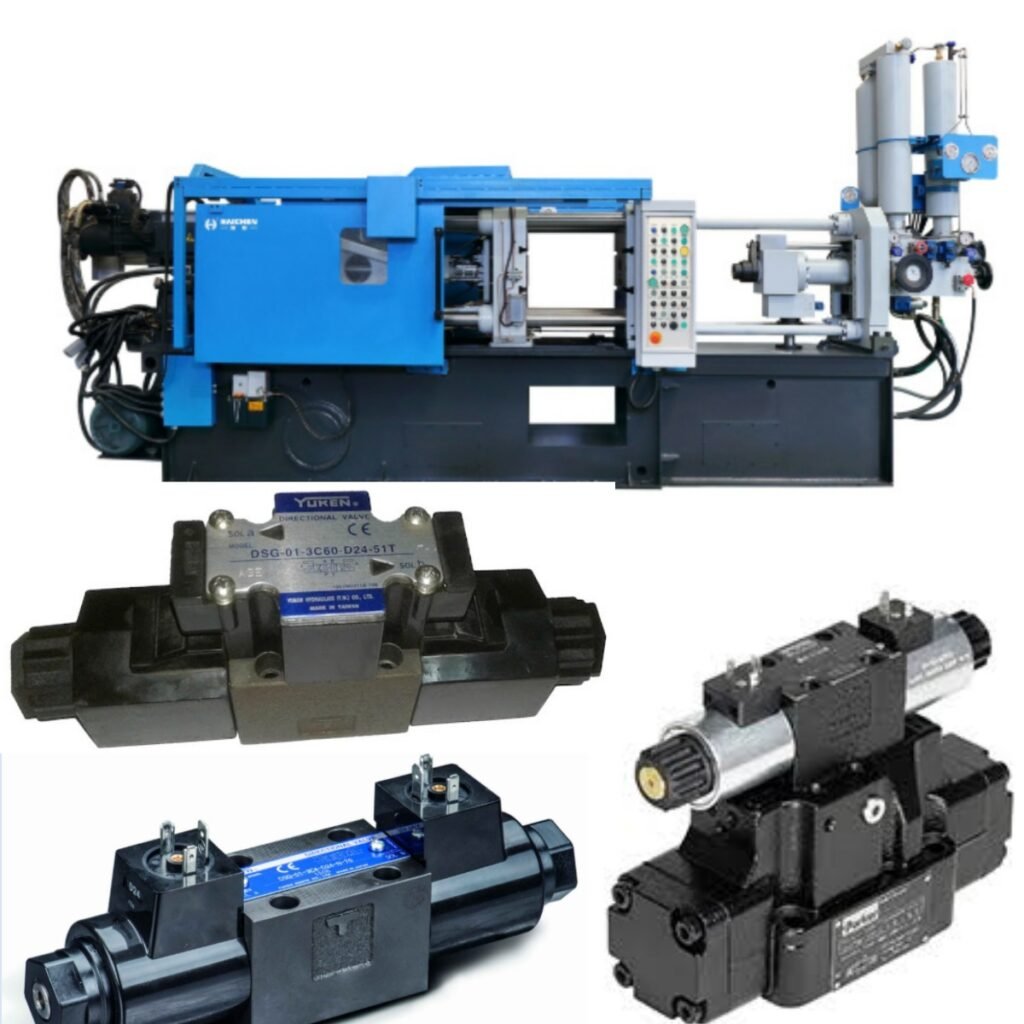
The basic function and composition of hydraulic valves
Hydraulic valves is the core control element of the hydraulic system of the die-casting machine.
Which is responsible for adjusting the flow, direction and pressure of the hydraulic oil to ensure that the actuator.
Such as hydraulic cylinder and hydraulic motor accurately completes the actions of mold closing, injection and ejection.
Hydraulic valves composition
Valve body and spool: spool, pop valve or ball valve structure, the fit gap directly affects the tightness.
Operating device: manual adjustment mechanism, solenoid or hydraulic drive for driving spool movement.
Auxiliary parts: seals, springs, solenoid coils, etc., to ensure the dynamic response and stability of the valve.
Common types of hydraulic valves
Directional control valve (such as reversing valve): control the oil circuit switching to achieve the action sequence.
Pressure control valves (e.g. relief valves): Regulate system pressure to prevent overload.
Flow Control Valve: Adjust the injection speed to adapt to different process stages.
Hydraulic valves are key components of hydraulic systems, responsible for regulating flow and pressure to ensure stable operation of equipment.
Valve failures can easily lead to system downtime and, in extreme cases, entire production lines.
Therefore, it is crucial to understand common hydraulic valve failures and their troubleshooting steps.
This not only helps detect faults faster but also minimizes downtime.
If you are not sure what is wrong with the hydraulic valve, you can contact Haichen to help you.
Analysis of common hydraulic valves fault types and causes
- Leakage failure
- Spool jamming or abnormal movement
- Abnormal pressure
- Corrosion and abrasion
Leakage failure
Internal Leakage: Seal failure due to spool wear, aging or contamination of the seal, manifested by insufficient system pressure or sluggish actuator.
External leakage: the sealing surface of the valve body is scratched or the bolts are loose, and the hydraulic oil seeps out to pollute the environment.
Spool jamming or abnormal movement
Mechanical Trapping: Oil contamination (metal debris, fibers) clogging spool damping holes or gaps.
Spring failure: Spring fatigue fracture or stiffness change, resulting in the spool not being able to reset.
Electromagnetic fault: coil burnout (voltage instability or overload), armature stuck, resulting in commutation failure.
Abnormal pressure
Pressure fluctuation: The damping orifice of the relief valve is clogged or the spool is deformed, causing the system pressure to be unstable.
Pressure cannot be established: Poor seal of the check valve (worn balls or scratched seats), resulting in backflow of oil.
Corrosion and abrasion
Chemical Corrosion: Acidic hydraulic fluids or humid environments can cause corrosion of the valve body, weakening the structural strength.
Furthermore, abrasive wear: Oil contamination accelerates the wear of the mating surface between the valve core and the valve body, increasing the amount of leakage.
Troubleshooting and repair processes
- Preliminary examination
- Disassembly and cleaning
- Washing steps
- Critical component inspection
- Functional testing
Preliminary examination
Observe symptoms: record abnormal phenomena (e.g., pressure gauge jitter, delayed movements).
System pressure test: Use the pressure gauge to detect the pressure of the main oil circuit to determine whether it is caused by valve failure.
Disassembly and cleaning
Relieving residual pressure: Switch the joystick in all directions to avoid oil jetting during disassembly. Marking & Recording: Mark the position of parts during disassembly to prevent assembly misalignment.
Washing steps
Rough cleaning: First, soak the valve body in diesel or a special solvent. Then, perform ultrasonic cleaning to remove large particles of impurities.
Fine cleaning: First, flush the valve core orifice with high-pressure cleaning liquid. Then, dry it with compressed air. Finally, apply anti-rust oil manually.
Critical component inspection
Valve core and valve body: check scratches and deformation, and the matching gap should be controlled at 0.008-0.015mm.
Seals: Replace O-rings and retaining rings that are aged or compressed and permanently deformed.
Springs and electromagnets: Measure the free length of the spring and test the resistance value of the solenoid coil.
Functional testing
Manual test: After assembly, manually push the valve core to confirm that the movement is smooth and free of stuckness.
Verification on the machine: After connecting to the system, the pressure is gradually pressurized to observe the pressure response and action accuracy.
Maintenance methods and technical points
- Cleaning process
- Seal Replacement
- Relief valve commissioning
Cleaning process
First of all, after disassembling the valve body, use kerosene or special cleaning agent to remove contaminants in the valve core and valve hole.
Then, focus on cleaning key parts such as damping holes and throttles.
Repair standard: The matching gap between the valve core and the valve hole should be ≤ 0.01mm, and the roughness Ra ≤ 0.4μm.
Seal Replacement
First, use an ultrasonic leak detector to locate the leak point.
Secondly, when replacing the seals, it is necessary to match the material
Such as fluoroelastomer high temperature resistance, nitrile rubber oil resistance.
Precautions: Apply hydraulic oil lubrication before assembly to avoid twisting or scratching the sealing surface.
Relief valve commissioning
Rotate the adjustment handle step by step and observe the pressure gauge pointer rising/falling smoothly (the pressure adjustment range should cover ±10% of the rated value).
Test at the highest pressure for 1 minute, the pressure offset value should be ≤2%.
Preventative maintenance methods
- Oil management
- Regular check-ups
- Environmental control
- Safety Precautions
Oil management
First, filter the hydraulic oil regularly (NAS Class 8 cleanliness) and change it every 3000 hours.
Monitor the oil temperature (50-60°C recommended) to avoid accelerated oxidation by high temperatures.
Regular check-ups
Monthly inspection: tighten the hydraulic line joints and check the nitrogen pressure of the accumulator.
Annual overhaul: complete dismantling and cleaning of the valve manifold, replacement of wear parts, calibration of proportional valve parameters.
Environmental control
First of all, keep the workshop clean to prevent dust from entering the tank.
It should be noted that in wet environments, it is necessary to use anti-rust hydraulic oil and add an air dryer.
Safety Precautions
Pressure Relief: Turn off the main pump and relieve pressure before maintenance to prevent residual pressure from triggering fuel injection.
Anti-pollution measures
Seal the oil port immediately when disassembling and clean it with a lint-free cloth.
Second, avoid using fiber cleaning tools to prevent residual debris.
Professional operation
Complex valve groups (such as proportional valves) need to be repaired by licensed personnel.
And it is forbidden to adjust the spring preload at will.
It should be noted that the power supply is disconnected when the solenoid valve is wired to prevent short-circuit electric shock.
Haichen‘s after-sales service
Hydraulic valve failure can easily lead to downtime of the entire system, so commissioning and repair must be carried out quickly.
If all common faults have been eliminated, consider possible specific faults depending on the specific model of the valve.
If you encounter any issues during the process, there is no need to worry.
Our engineers are ready to provide professional after-sales service and one-stop solutions, tailored to your on-site situation, to resume your production as soon as possible.