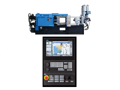
Tie bars form a very important structural member of a die casting machine. They are used to connect the platens and at the same time generate clamping force which keeps the mold closed during high-pressure injection.
Such bars and rods find their typical application in die casting machines, hydraulic presses, or any other four-column press that demands rigid structure in harsh environments.
The problem most frequently associated with the die casting process involves the tie rods of a die casting machine. The tie rod forms an integral part of the connection between the two halves of a die casting mold. Its main duty includes pressure transmission to keep the mold closed.
Introduction to Die Casting Tie bars
Let’s disassemble the details and functions of the die casting machine tie rod step by step.
Below is a detailed breakdown:
- Tie bars in die casting’s Structure and Positioning
- Key Functions
- Design and Material Considerations
- Operational and Maintenance Guidelines
- Technological Advancements
- Practical Applications
Tie bars in die casting’s Structure and Positioning
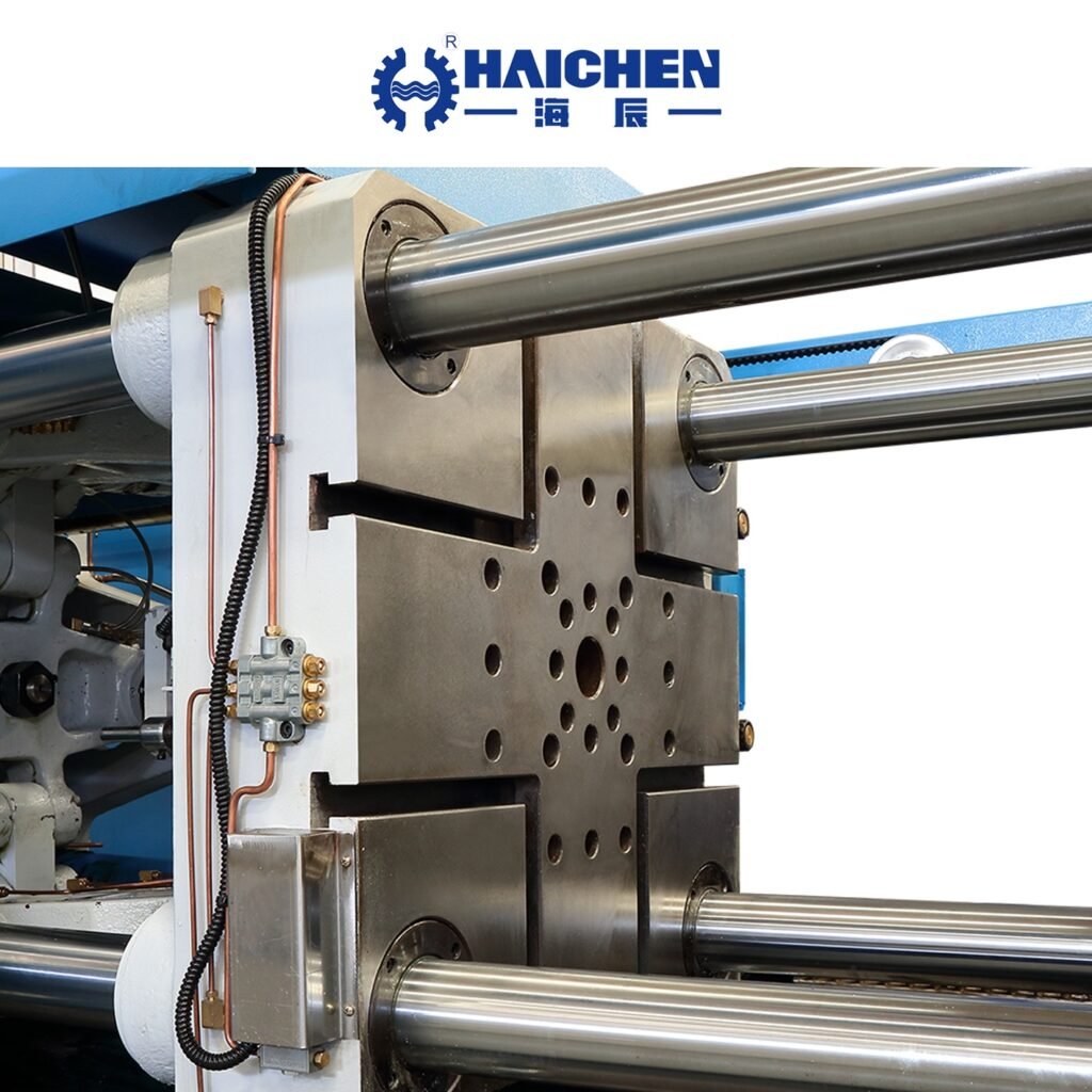
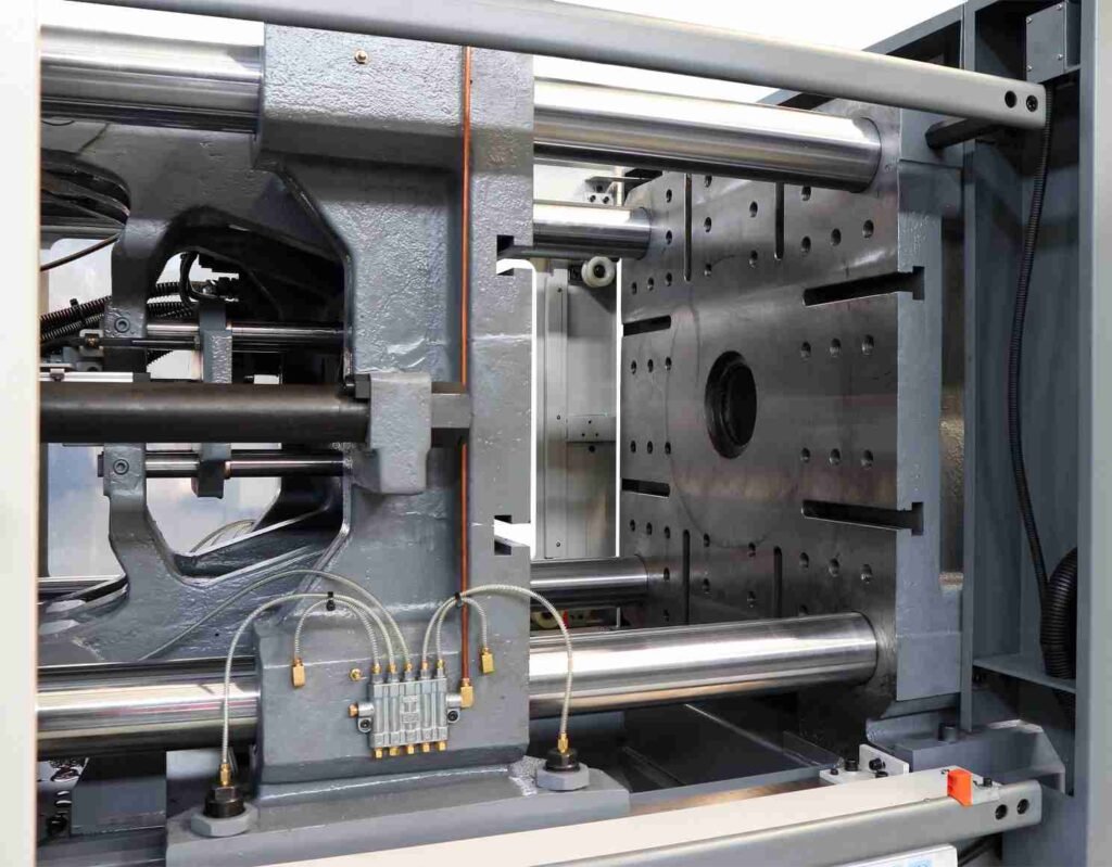
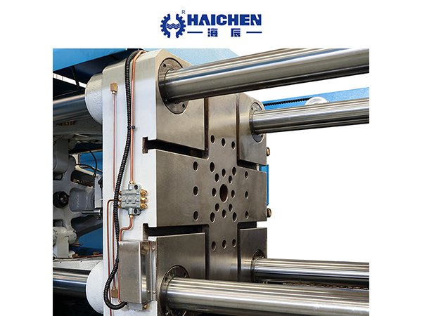
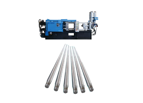
- Design: Tie bars are robust cylindrical steel rods, typically four in number, positioned at the four corners of the machine’s platens.
- Installation: They connect the stationary platen (fixed) and moving platen (slides along the tie bars to open/close the mold).
Key Functions
- Clamping Force Generation: During operation, tie bars stretch elastically to produce clamping force. For example, each tie bar in a 400-ton machine withstands ~100 tons of tension, with the total force distributed across all four bars.
- Resisting Injection Pressure: Tie bars counteract the internal mold pressure (often hundreds to thousands of bar) from molten metal injection, preventing mold separation.
- Machine Capacity: Tie bar diameter, length, and material strength determine the machine’s maximum clamping force and compatible mold sizes.
Design and Material Considerations
- Material: High-strength alloy steels (e.g., Grade 355 or 460) are commonly used. Surface treatments like nitriding or chrome plating enhance wear and corrosion resistance. Advanced designs feature full floating tie bars to improve stability and longevity.
- Strength Calculations: Compliance with standards like EN 1993-5 ensures tie bars are sized based on minimum cross-sectional area (threads or shaft) and account for additional stresses (e.g., uneven mold loading).
4. Operational and Maintenance Guidelines
- Strain Monitoring: Regular checks for elongation (strain) are critical. A 10-foot tie bar with 0.001 in./in. strain stretches ~0.12 inches (~3 mm). Abnormal strain may indicate uneven clamping or mold misalignment.
- Failure Risks: Overstretching due to incorrect settings (e.g., excessive mold thickness or clamping force) can lead to tie bar fractures, risking operational safety.
Technological Advancements
- Smart Compensation: Modern machines (e.g., TFs Toggle Free series) balance tie bar loads and auto-correct mold geometry deviations, integrating intelligent injection controls to reduce defects.
- Simulation Tools: Finite Element Analysis (FEA) and empirical models (e.g., power-law models) optimize tie bar load distribution by predicting asymmetric stresses, improving mold pressure alignment.
Practical Applications
- Mold Compatibility: Mold dimensions must fit within the tie bar spacing (e.g., a 350-ton machine may have 650×650 mm spacing). Oversized molds require larger machines.
- High-Capacity Machines: Heavy-duty machines (e.g., 4000-ton clamping force, 1780×1780 mm spacing) are used for automotive structural components like engine blocks.
Tie bars are indispensable for maintaining structural integrity and safety in die casting. Advances in materials, smart load management, and simulation-driven designs are enhancing their efficiency and durability. Rigorous monitoring and alignment with process parameters ensure optimal performance and high-quality castings in modern die casting operations.
Tie Bar Load Calculation in Die Casting
In die casting, tie bar load calculation requires comprehensive consideration of material mechanics, geometric positioning, and practical operating conditions.
Below is a detailed analysis:
- Fundamental Calculation Formula
- Load Distribution and Shot Centroid Position
- Practical Measurement and Monitoring
- Influencing Factors and Optimization
- Safety and Standards
Fundamental Calculation Formula
The core formula for tie bar load is:
Ftb=ε⋅Atb⋅EFtb=ε⋅Atb⋅E
Where:
- εε: Strain (unit elongation, e.g., 0.0005 in./in.).
- AtbAtb: Cross-sectional area of the tie bar, calculated as:
Atb=π⋅Dtb24Atb=π⋅4Dtb2
Here, DtbDtb is the tie bar diameter. - EE: Modulus of elasticity of steel (30,000,000 psi or 207 GPa).
Example: For a tie bar diameter of 2 inches and strain of 0.0005 in./in.:
Atb=π⋅(22)/4=3.14 in2Atb=π⋅(22)/4=3.14in2
Ftb=0.0005⋅3.14⋅30,000,000=47,100 lbs or 23.55 tonsFtb=0.0005⋅3.14⋅30,000,000=47,100lbsor23.55tons
Load Distribution and Shot Centroid Position
Tie bar load distribution is significantly influenced by the position of the mold’s shot centroid:
- Formula:
Fx=F⋅(W−X)W⋅(H−Y)Fx=F⋅W⋅(H−Y)(W−X)
Where:- FF: Total clamping force.
- WW and HH: Distance between tie bar centers.
- XX and YY: Offset of the shot centroid relative to the machine center.
Example: A horizontal offset of 1 mm in the shot centroid may increase the corresponding tie bar load by 0.25 tons. Optimizing the shot centroid position balances loads across tie bars, preventing localized overloading and flash defects.
Practical Measurement and Monitoring

- Strain Measurement:
Common methods include hole-drilling (measuring elongation depth) or magnetic dial indicators. Modern systems use ultrasonic strain gauges or wireless sensors (e.g., Gefran QE2008-W) for real-time Bluetooth monitoring of elongation with higher precision. - Sensor Applications:
Strain sensors are typically installed on each tie bar in die-casting machines to directly monitor tension changes. For example, in a 900-ton clamping force machine, each tie bar is designed to carry 225 tons (assuming four tie bars evenly share the load).
Influencing Factors and Optimization
- Thermal Effects:
Thermal expansion alters mold dimensions, affecting tie bar strain and load distribution. Regular calibration is required. - Mold Support Structures:
Small molds in large-tonnage machines may require spacer blocks or L-shaped supports to reduce localized stress concentrations. - Finite Element Analysis (FEA):
Nonlinear power law models can predict tie bar loads, with experimental validation showing errors between 0.1% and 12%, making them suitable for complex scenarios.
Safety and Standards
- Overload Protection:
Modern die-casting machines incorporate tie bar stress protection mechanisms, such as proportional valve-controlled clamping force, to prevent uneven loads and fractures. - Design Standards:
Tie bar spacing, support angles (e.g., 30°–50° triangular arrangements), and material strength must comply with industry standards (e.g., GB50017, CJJ37-90) to ensure structural stability.
Tie bars load calculation in die casting combines material mechanics (strain-stress relationships), geometric adjustments of the shot centroid, and real-time monitoring. Practical considerations include thermal effects, mold alignment, and support structures. Integrating theoretical calculations with experimental validation (e.g., FEA) optimizes load distribution and prevents flash defects.


