Die casting machine tie bars break because excessive mechnical stress, metarial and design issues, production speed and mold design and so on.
The core of tie rod breakage is unbalanced stress distribution leading to single overload, rather than uniform overload. Root causes include tool/machine misalignment, uncompensated thermal deformation, uncontrolled flash and lack of maintenance. The risk of breakage can be significantly reduced through automatic tension control, strict calibration and high toughness materials.
The reasons for the fracture of the connecting rod (Tie Bar) of the die casting machine can be analyzed from multiple aspects:
- Excessive mechanical stress of die casting machine tie bars break
- Material and design issues
- Production speed and mold design
- Other external factors
Excessive mechanical stress of die casting machine tie bars break
- Unbalanced load
- Fatigue damage and stress concentration
- Operation and maintenance factors
- Thermal effect and deformation
During the die casting process, the connecting rod needs to withstand huge mechanical stress. For example, the clamping force of the cold chamber die casting machine can reach thousands of tons. It requires the connecting rod to have sufficient strength and rigidity to withstand such pressure. If the material or design of the connecting rod fails to meet these requirements, it may cause it to break.
Unbalanced load
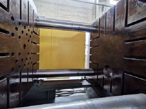
- When there are design defects in the mold, the installation position is offset, or the machine is not leveled, the clamping force cannot be evenly distributed to the four tie rods, causing a single tie rod to bear a stress exceeding 1/4 of its design load (such as exceeding the material yield strength of 90kN/mm²).
- For example: when the mold cavity is off-center, the mold support surface is uneven (such as the “coining effect”), or the machine foundation is not level, it will force a certain tie rod to bear a larger proportion of the load.
Fatigue damage and stress concentration
- The tie rod is subjected to alternating stress during the cyclic clamping process. If there are surface scratches, thread damage, improper heat treatment, or internal defects in the material (inclusions, cracks), stress concentration points will be formed, accelerating fatigue fracture.
- The case analysis shows that the superposition of thermal stress and microstructural stress caused by improper heat treatment causes crack propagation under continuous tensile force.
Operation and maintenance factors
- Flash problem: Excessive flash causes the mold to close loosely, requiring greater clamping force when clamping, which intensifies the stretching of the tie rod; at the same time, the flash embedded in the mold surface will further destroy the force balance and directly cause the tie rod to break.
- Lack of daily maintenance: Loosening or thread wear of the tie rod nut (“slop effect”) will cause imbalance in the distribution of clamping force, and it is emphasized that the tightening status of the nut should be checked daily.
- Overload operation: Forcibly producing large molds on machines with insufficient tonnage (such as 1100-ton molds for 1000-ton equipment), resulting in systemic overload.
Thermal effect and deformation
- The temperature rise of the mold (such as a 100°F temperature rise makes the 72-inch mold thicker by 0.045 inches) causes uneven thermal expansion of the tie rod. If the tension is not adjusted in real time, it will cause local overload.
- The difference in the length of the four tie rods will amplify the temperature strain, causing the longer tie rod to break under the constraint of thermal stress.
Material and design issues
- Inherent defects in materials
- Insufficient strength
- Stress concentration
- Connection design
- Unloading groove design
The material and design of the connecting rod are important factors affecting its life. If the material strength is insufficient or the design is unreasonable.
Such as the bolts are too tight or too loose. It may cause the connecting rod to fail under high pressure or vibration conditions. In addition, the surface treatment and manufacturing quality of the connecting rod may also affect its performance.
Inherent defects in materials
- The breakage of tie rods at specific locations is often due to metallurgical defects in the material, such as cracks, inclusions, uneven alloy composition or improper heat treatment.
- These defects form stress concentration points, resulting in a decrease in local load-bearing capacity.
- High-strength steels (such as yield strength > 500MPa) may suffer from stress corrosion cracking (SCC), especially in highly corrosive environments (such as seawater), which require additional protection.
Insufficient strength
- Tie rod stress calculation formula: Stress = clamping force × 1000 / (3.14 × diameter²).
- If the design strength is insufficient (such as wrong material selection or too small diameter), or the actual clamping force exceeds the material limit (such as a 1000-ton machine forcing a 1100-ton mold), it will cause overload fracture.
Stress concentration
Design defects such as sudden change in stepped shaft diameter, missing transition fillet, large surface roughness of thread, and improper heat treatment can easily cause fatigue fracture.
Connection design
The thread area is the weakest point. The cross-sectional area of the cold-rolled thread is smaller than the rod body. It is recommended to use the upsetting process (Upset forging) to increase the cross-sectional area of the thread so that the fracture occurs first in the rod body rather than the thread.
Unloading groove design
- Unoptimized unloading groove parameters in the injection molding machine (such as the ratio of groove diameter to tie rod diameter) will lead to unbalanced bending deformation.
Thermal coupling failure - Uneven mold temperature (unreasonable cooling design) or thermal shock of molten metal causes thermal stress cycles in the tie rod, causing low-cycle fatigue fracture.
Thermal expansion causes the mold to deviate from the parallel position, resulting in uneven load distribution.
Solution of die casting machine tie bars break material and design issues
Design optimization
- Use upsetting threads to increase connection strength.
- Optimize unloading groove parameters (such as diameter ratio) to balance loads.
- Add articulated joints to compensate for foundation settlement deformation.
Material upgrade
- Select high-toughness alloy steel (such as H13 hot-working die steel) with a hardness of 30-37HRC and hard chrome plating (69-72HRC) on the surface to enhance wear and corrosion resistance.
- Avoid using high-strength steel (>800MPa) to prevent uncontrolled fracture.
Maintenance and monitoring
- Check the tightening status of the nut daily.
- Regularly use the “Squaring block” to check the parallelism of the machine.
- Install an automatic pressure regulating system to compensate for tension changes caused by thermal deformation in real time.
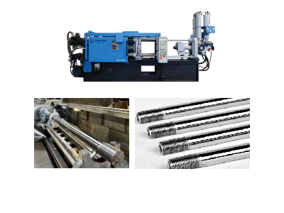
Repair technology
- Broken tie rods can be repaired by welding + precision machining + heat treatment, which is 30%-50% lower in cost than replacement.
- Surface polishing or chrome plating to repair worn areas.
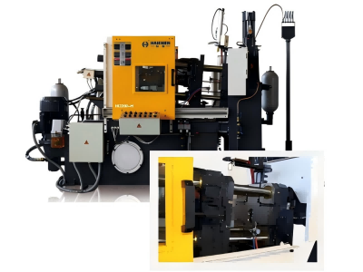
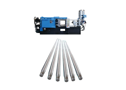
Haichen, one Chinese die casting machine manufacture for more than 10year. Their proactive control of die casting machine tie bars break begins with using premium, high-tensile alloy steel bars and precision manufacturing to ensure inherent strength and uniform load distribution.
During operation, Haichen uses an advanced real-time clamping force monitoring system constantly checks for imbalance or overload, automatically alerting operators or adjusting the process. For problem-solving, Haichen provides detailed diagnostic protocols to identify root causes—such as improper die alignment or excessive locking force—and supports precise re-tensioning procedures or rapid replacement with genuine, matched components to restore optimal machine integrity and prevent recurrence.
Production speed and mold design
- Uneven force or overload
- Material and maintenance issues
High-speed production will cause the connecting rod to bear greater mechanical loads. If the mold design is unreasonable. Such as the cavity wall is too thin or the material has good fluidity but a large forming area. The stress on the connecting rod may increase. In addition, the symmetry of the mold and the design of the fixing points will also affect the force distribution of the connecting rod.
Uneven force or overload
The main reason for the tie rod to break is that the load on a single tie rod exceeds its ultimate strength, which is usually caused by misalignment of the machine or mold. Specifically, it includes:
- Mold design defects lead to uneven pressure distribution (such as skewed cavity position);
- The machine is not installed horizontally or the foundation is unstable, and it loses balance during dynamic operation;
- Long-term wear (such as loose threads) causes uneven force on the tie rod.Overload operation (for example, a mold with a clamping force of 1,100 tons running on a 1,000-ton machine) will directly cause the tie rod to break due to overload.
Material and maintenance issues
Metallurgical defects (cracks, inclusions) or corrosion of the tie rod itself may reduce its strength;
Lack of regular maintenance (such as failure to use a “square block” to detect machine parallelism) will accelerate the occurrence of problems.
Other external factors
- Insufficient lubrication
- Aging and maintenance issues
Mismatch or failure of other parts of the die casting machine (such as molds, push rods, etc.) may also indirectly affect the stress state of the connecting rod. For example, a slight deviation of the mold may cause the connecting rod to bear uneven stress.
Insufficient lubrication
During the die casting process, proper lubrication can reduce mechanical stress and wear. If the lubrication is insufficient, it may cause the connecting rod to be damaged due to friction and high temperature.
Aging and maintenance issues
Long-term use of connecting rods can lead to material fatigue and aging, which reduces their strength and toughness. Improper maintenance, such as failure to replace worn parts in a timely manner or failure to conduct regular inspections, can also accelerate the breakage of connecting rods.
The reasons for the fracture of the connecting rod of the die casting machine are usually multifaceted. Including excessive mechanical stress, material and design problems, unreasonable production speed. And also mold design, insufficient lubrication, aging and improper maintenance, and other external factors. In order to reduce the risk of connecting rod fracture, it is necessary to comprehensively consider multiple aspects such as material selection, design optimization, production control and maintenance management.


