Tie bar load calculation in the die casting process, the tie rod is a key connecting component between the die casting machine and the mold.
And it is directly related to the safety of the equipment and the quality of the casting.
Tie bar load calculation in die casting is crucial for ensuring the structural integrity of the machine and the quality of the cast parts.
It involves determining the force that the tie bars, which hold the die halves together, must withstand during the casting process.
This calculation considers the clamping force of the machine, the projected area of the die cavity.
And the distribution of these forces across the tie bars.
Understanding Tie Bars and Their Role
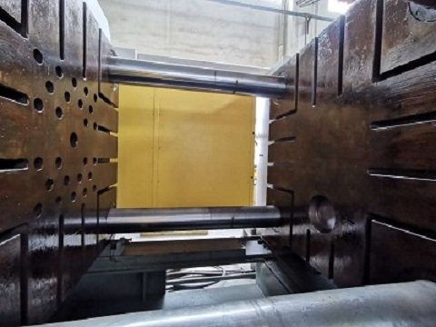
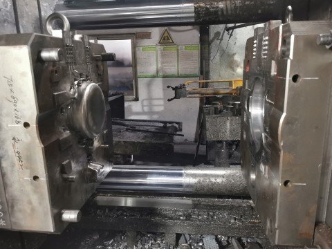
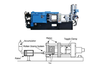
Tie bars are the structural components that connect the moving and stationary platens of a die casting machine.
They are essential for resisting the clamping force generated during the injection of molten metal into the die.
Uneven tie bar loading can lead to issues like flash excess metal at the parting line, die deflection, and even tie bar failure.
The function and structural characteristics of the tie rod
The tie rod also known as the Colin column of the die-casting machine is mainly used to bear the clamping force.
To ensure that the mold remains rigidly closed during the high-pressure filling process.
The number is usually 4, and it is symmetrically distributed at the four corners of the die casting machine template to form a closed frame structure.
Tie rod structure parameters
Diameter: 70mm (100T small machine) to 180mm (800T large machine).
Spacing: For example, the inner spacing of the tie rod of J1115 die-casting machine is 420×420mm, while the SJ800 type is 910×910mm.
Material: Usually made of high-quality alloy steel (such as 42CrMo4), quenched and tempered (QT process), the yield strength ≥ 500MPa, and the tensile strength ≥700MPa.
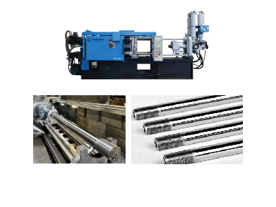
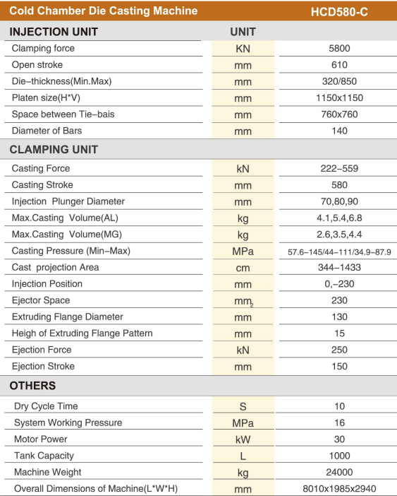
The following are the 580-ton parameters of the Haichen cold chamber die-casting machine for your reference.
Detailed explanation of the load calculation of Tie Bar in die-casting
- Connecting template
- Withstanding Expansion Force
- Maintain mold clamping accuracy
Connecting template
Through four tie rods, the fixed platen, the moving template and the frame are connected into a rigid structure.
Withstanding Expansion Force
During the injection process, the molten metal is injected into the cavity at a high pressure typically 400-800 bar.
And the resulting opening force is counteracted by the tensile stress of the tie rod.
Maintain mold clamping accuracy
The stiffness of the tie rod directly affects the closing stability of the mold parting surface.
And uneven load will lead to flash, mold deformation and other problems.
The core formula of tie rod load calculation
The load of tie rod is directly related to the clamping force.
And the calculation formula needs to comprehensively consider the following parameters.
- Total projection area (A)
- Filling pressure (p)
- Clamping force (F)
Total projection area (A)
The area of the sprue system is usually 15%-30% of the projection area of the casting, and the area of the overflow system is 10%-20%.
Filling pressure (p)
In aluminum alloy die-casting, the filling pressure is selected according to the application.
Appearance parts: 500-600 kg/cm²
Non-sand hole parts: 600-800 kg/cm² Pressure-resistant parts: 800-1000 kg/cm²
Clamping force (F)
The compensation coefficient K is taken as 1.2-1.4 to cover dynamic shocks and load fluctuations.
If the casting has a projection area of 2000 cm², a sprue area of 20% (400 cm²), an overflow area of 15% (300 cm²).
And a filling pressure of 600 bar, the total clamping force is: A die-casting machine with a clamping force of ≥ 2106 tons is required.
Why is clamping force calculation necessary in die casting?
A small clamping force can lead to poor geometrical symmetry and flashes.
In addition, hotshots, loose packing, and air bubbles result from that force.
A large clamping force can cause insufficient air venting during mould filling/packing, premature ageing of hydraulic components, and mechanical structural wear.
Moreover, too much clamp force increases machine energy, hikes energy costs, deflects the platen and reduces mould life.
Therefore, Haichen will ensure that the clamping force applied is accurate and precise, so that the casting can be completed successfully.
How does the automatic tie rod load adjustment system achieve closed-loop control in die casting machines?
The die-casting machine of Haichen, the automatic linkage load regulation system adopts a closed-loop control method to precisely control the load.
Specifically, this system continuously monitors and adjusts the load of the linkage to keep it consistent with the preset target.
Thereby ensuring the stability of the production process and the quality of the products.
The implementation involves these key steps:
- Sensor Monitoring
- Signal Processing & Comparison
- Actuator Response
- Feedback Adjustment
- System Optimization
Sensor Monitoring
High-precision load cells or pressure sensors first detect real-time tie rod loads.
These devices convert actual load data into electrical signals and transmit them to the control system.
Signal Processing & Comparison
Subsequently, the control system compares sensor signals with target load values.
When deviations occur, it calculates error values and generates corresponding control commands.
Actuator Response
Based on these commands, actuators (e.g., servo motors or hydraulic valves) apply force/pressure to minimize errors. For instance:
If actual load < target → actuators increase tension
Conversely, if actual load > target → actuators reduce tension
Feedback Adjustment
After actuator intervention, sensors immediately capture updated load data.
This cycle repeats until loads stabilize near target values, forming the core of closed-loop control.
System Optimization
Furthermore, modern systems incorporate adaptive algorithms.
These continuously optimize control strategies for varying materials, molds, and parameters, ensuring robustness in dynamic production environments.